Current Mirror
Note
One thing that is glossed over here is that for this to be accurate, you'll need well matched transistors. Without that, the currents will not be matched tightly. Current mirrors are heavily used as current sources inside integrated circuits where you have easily matched transistors.
A current mirror is a current source circuit that can be "programmed" to mirror current between one side that you program and another side that you want to control. Take the following circuit, for example:
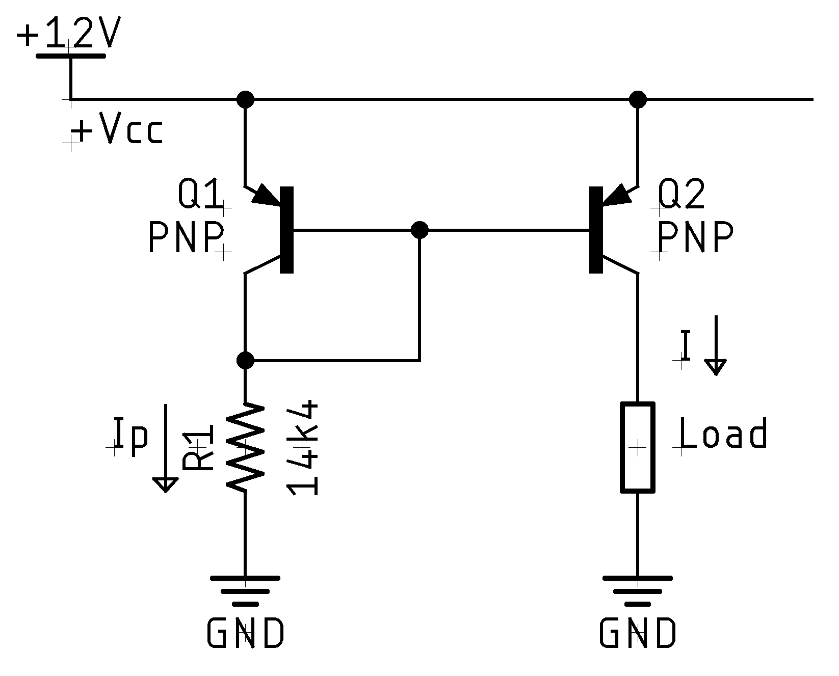
On the left side, you have the programmed side of the circuit. You program Q1 by sinking a current (Ip) from Q1's collector (note these are PNP, not the more typical NPN transistors) via R1. That causes a Vbe (voltage between base and emitter) for Q. The linkage between Q1 and Q2 causes a "mirrored" current (I) to be materialized.
To calculate R1, though, we need to take into account the voltage drop on the base of Q1. Typically this is close to the same as a diode (0.6V), so with a 14.4K resistor, we will get:
See, there's that pesky Ohm's law.
Current mirrors are insanely useful in transistor circuits. For example, there are many op-amps which use an external resistor to set the operating current for the whole amplifier using multiple current mirrors internally.
Improved Load Stability
You can improve the load stability of this current mirror by slightly modifying it, adding an additional transistor, and forming a Wilson mirror. If you need more than a tiny handful of milliamps (mA), then you should consider this.
Comments or Questions?
If you have any comments, questions, or topics you'd like to see covered, please feel free to either reach out to me on Mastodon (link below) or open an issue on Github.