Fundamentals
None of this is unique, original, or otherwise only found here, but I thought it might be useful to collect things that people should probably know about.
Before we jump into anything else, we should get some basics out of the way. For a long time, I found the difference between voltage and current to be confusing, not least because people seemed obsessed with voltage, when current is the thing under it all. So let's start with current.
Non-intuitive Stuff to Think About
Elsewhere, I talk about the non-intuitive idea of electron flow, but for the purposes of this and most use cases, it doesn't matter. Only if you want to be technically correct.
Current (volume)
Current is, fundamentally, flow. It is the rate at which electrons flow past a specific point in a complete electrical circuit. A circuit is considered complete if there is a path for all electrons to flow in a "loop". Any component that converts electrical energy into some other form of energy (rotation, heat, light, even "processing") uses current.
We measure current in ampere, or more often shortened to just amp. It expresses the quantity of electrons (aka electrical charge) flowing past a point in a circuit over a give time. A current of 1 amp can be translated as 1 coulomb of electrons, or 6.24 x 10¹⁸ electrons moving past a single point in one second. It is traditional to compare electricity to water, and in this case, you'd talk about how many liters pass a single point in a hose in 1 minute (liter per minute). We use a few measurements regularly:
- A. Amperes (amps) for large amounts of current. You will typically only see a small number of these in most applications, but in things like electric cars, you might see hundreds of amps. High currents can be very dangerous.
- mA. Milliampere (milliamp) is a typical unit in electronic circuits that you'll work with. This is 0.001 ampere.
- µA. Microampere (microamps), or a millionth of an amp (0.000001).
There are smaller units, like picoamps, but outside of a very few specialized applications, you'll never see them, and you likely can't afford a device that can reliably even measure them. You can, if needed, construct a circuit to sneak up on the value, though.
You will also see current referred to as I in things like Ohm's law (below). For the longest time, I had no idea why "I" was used, but it refers to the "intensity". For current to flow, two things must be true:
- A circuit that forms a closed conducting loop. This provides a loop through which electrons can flow, and therefore providing energy (electrons) to components along the loop. You can think of a loop (circuit) as closed when you flip a light switch to the on position.
- The circuit must include a source of energy, such as a battery, that produces voltage. Without voltage, electrons move randomly and evenly within a wire, and therefore no current is flowing (think of still pond water). When voltage creates pressure that will drive the electrons in a single direction, like a stream.
Current comes in two forms: direct current (DC) and alternating current (AC). DC is what most electronics work with, and AC is what your house runs on. DC flows in a single direction, and therefore we can often talk about positive and negative connections. AC, as the name implies, alternates back and forth (a sine wave, technically) on a regular interval (60Hz in the United States, for example), and so we don't talk about positive and negative, but typically (at least in the US) "hot", "neutral", and "ground". Yes, it is not particularly obvious at first. This article might help, but typically, you won't be dealing with a lot of AC outside pre-built power supplies.
Wire Gauge and Current
Many things are sized based on the current with a much broader voltage range. For example, if we use the AWG wire standard, we can see that while 16 gauge solid core wire can carry a maximum of 15A, a 24 gauge 7-strand wire can only handle 1.4A. Typically, wire smaller than 24 gauge (i.e., with a larger gauge number) is treated as "signal wire", and only designed to carry tiny amounts of signal voltage (µA). This is also why on a PCB, we often need to use a trace width calculator.
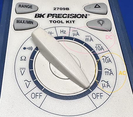
We measure current with a multimeter most of the time. If we look at my trusty BK 2709B, we can see two different things. First, there are two different sections for measuring current, one for AC and another for DC. Second, while this multimeter is technically auto-ranging, you do have to tell it what magnitude of current to expect. This is for internal safety protections, and at least on my BK, while µA and mA use the same connector, the 10A measurement uses a different connector completely (and has different protection mechanisms inside).
Voltage (pressure)
If current is the volume of electrons passing a point in a circuit, voltage is the pressure. To continue the water analogy, if current is the liters per minute, voltage is the pressure behind it where we measure water in (typically) either pounds per square inch (psi) or Pascals (Pa). We measure the voltage pressure in volts (V), which is named after Alessandro Volta, who invented the early precursor of the battery. You might occasionally hear voltage termed as electromotive force (EMF), which is why you'll sometimes see voltage expressed as the variable E. Mostly, the term comes up in discussions of back EMF.
We often use the term voltage and potential difference interchangeably. Volts is the unit we use to express the potential energy difference between two points in a circuit. Potential energy is the potential to move electrons from one point to another, and because of that voltage exists only relatively. You cannot measure voltage at a point. You can only measure voltage between two points. This took me a long time to grasp because it's not super intuitive. The greater the voltage, the greater the ability to "push" more electrons and do more work.
Like current, voltage comes in both direct and alternating forms. While this actually refers to the nature of the current that the voltage is moving, when measuring voltage, we need to deal with DC voltage (VDC) and AC voltage (VAC) differently, and if you look at the multimeter dial above, you can see there are similar settings for AC and DC voltage measurement.
Power
In addition to the two fundamental measurements, voltage and current, we often talk about power (P). Power is the rate of energy transfer and is measured in joules/second. We also call them Watts (W). As you can see in Ohm's Law below, \(P=V\cdot I\), which means it's just voltage times current.
Resistance
While it may sound negative, resistance is a fundamental property of electronics nd is critical to any functioning circuit. Resistance is a measure of the opposition to current flow in an electrical circuit. It is measured in ohms, which is represented by the Greek letter omega (Ω). It is often represented in equations as the letter R.
All materials resist current flow to some degree. They fall into one of two broad categories:
- Conductors
- Materials that offer very little resistance where electrons can move easily. Examples: silver, copper, gold and aluminum.
- Insulators
- Materials that present high resistance and restrict the flow of electrons. Examples: Rubber, paper, glass, wood and plastic.
The higher the resistance, the lower the current flow; resistance is the primary reason all conductors give off some degree of heat, so overheating is an issue often associated with resistance. The lower the resistance, the higher the current flow.
Many components, such as resistors, have a fixed-resistance value. Resistance is a property of the materials being used, as well as their physical dimensions. You can calculate the resistance as:
where \(A\) is the cross-sectional area (in meters), and \(L\) is the length (also in meters). \(\rho\) is the intrinsic resistive property of the material, although it does change with temperature.
For example, here's a few different materials and their \(\rho\) values:
| Material | \(\rho\) at 20C |
|---|---|
| Copper | \(1.68\times 10^{-8}\) |
| Aluminum | \(2.82\times 10^{-8}\) |
| Iron | \(1.0\times 10^{-7}\) |
| Sea water | \(2.0\times 10^{-1}\) |
| Air | \(2.3\times 10^{16}\) (approximately) |
So, for a 10cm length of 26ga solid core copper wire (don't you love mixing weird measurement units), you could calculate this using the equation earlier:
This means that our 10cm length of wire has a resistance of 0.012Ω. Note that stranded wire would have a slightly different value which is the aggregate of the cross-section of each strand multiplied by the number of strands.
Equivalent Source Resistance (ESR)
Often, you will hear people talk bout the the ESR of a component. For example, when you have a voltage divider (see here), and you attach a load which has some resistance, the voltage will actually drop due to a finite source resistance. ESR refers to the hypothetical Thevenin equivalent resistance of the circuit . Nearly everything has an ESR, and there are tools, such as LCR meters, that can help you determine it if it's not provided on a datasheet.
The undesirable reduction of voltage mentioned above is a result of what is called circuit loading, and what designers mean when they refer to the load of a circuit. As a general rule, you want to keep \(R_{\mathrm{load}} \gg R_{\mathrm{internal}}\) as a high-resistance load has little effect on the source. This is one reason you will see things like multimeters with resistance measured in the megohms.
Capacitance
Capacitance is the ability of a component or circuit to collect and store energy in the form of an electrical charge. We measure this charge as the ratio of the electric charge on each conductor to the potential difference (i.e., voltage) between them. The value is measured in farads (F), units named for English physicist Michael Faraday. A farad is a large quantity of capacitance. Most electrical devices include capacitors that produce only a fraction of a farad, often a thousandth of a farad (or microfarad, µF) or as small as a picofarad (a trillionth, pF).
Safety with Capacitance
Because capacitors, by definition, store electrical charge, and that charge can be substantial, it is critically important to ensure you discharge any capacitor before you might come into contact with it. While this is probably not important for capacitors in the pico or nano Farad range, by the time you hit a micro (µ) farad, you're looking for trouble.
The best way to discharge a capacitor, if you don't want to do the math is using a little homemade discharge tool (example to come, sorry).
Inductance
Hand Waving Ahead
I find inductance to be one of the most complicated subjects in electronics, and I will attest to not being 100% comfortable that I understand it completely. So, I'm going to try and explain it how I understand it, and how I think about it. This is likely not 100% correct, but it is hopefully 84% useful.
While many of the preceding characteristics are true of both fixed/constant currents and alternating currents, inductance is, effectively, purely about alternating currents. Inductance is the characteristic of an electrical component which opposes changes in current. We measure inductance in Henries (H), and typically use the symbol L to represent them. One Henry is a lot of inductance.
I like to think of inductance as the inertia of a component in the circuit. Inertia is the characteristic of mass which opposes a change in velocity. Inductance does the same thing in an electrical circuit. This means that it requires more energy to start or stop the flow of current than it does to maintain it.
Every conductor has some inductance. This is because current in a conductor will always produce a magnetic field surrounding the conductor (see Faraday's Law). When the current changes, the magnetic field changes, which will induce an electromotive force (EMF). For reasons I don't 100% understand, this is always counter to the applied voltage, creating the inductance or opposition to change. This is defined by Lenz' Law, which states:
The current induced in a circuit due to a change in a magnetic field is directed to oppose the change in [magnetic] flux and to exert a mechanical force which opposes the motion.
Inductance comes in two forms: self-inductance and mutual-inductance. Put simply, self-inductance is when one conductor induces inductance in itself. Mutual-inductance is when one conductor also induces inductance in another conductor. Examples of mutual inductance include motors, transformers, and solenoids.
There's a lot of math, but I think that if you understand that it is about the opposition to changes in current you'll get reasonably far.
Impedance
Complex Numbers Ahead
I'm going to try and avoid the complex numbers as much as possible, but it's not totally avoidable when talking about impedance. At some point, I'll likely dive more deeply into this topic, but that'll be a topic for another page.
When a circuit has capacitors and inductors in it, it is more complicated than a purely resistive circuit. Unlike resistors, capacitors and inductors change behavior depending on frequency. This is why we consider these to be reactive. This results in a much more complex model for analyzing them.
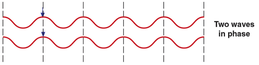
Impedance (Z) is "generalized resistance". For something like a resistor, we find the voltage and current in phase.
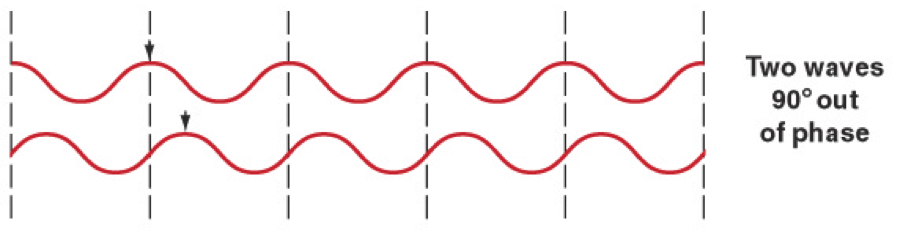
However, for reactive components (inductors and capacitors), the voltage and current are out-of-phase (90° typically) from each other.
We call the out-of-phase behavior reactance (X), and the in-phase behavior resistance (R).
Since most circuits combine both types of components, the phase relationship of voltage and current will be different in different parts of the circuit. This is also where the complex numbers start to rear their ugly heads. We can have in-between phase alignments (not 0° and not 90°). To represent that combination of resistance and reactance, we use the term impedance, which is represented as:
See, there's the imaginary part (j). This is also where you'll start seeing ω pop up all over the place. The omega (ω) is the angular velocity (change in angle over time). So, if we look at the impedance of the fundamental components (resistors, capacitors, inductors), we get the following equations based on their behavior:
This reactance is why filters work the way they do. It's why blocking capacitors work. It's why decoupling works. For now, I'll send you to read §1.7 in Art of Electronics: Third Edition. Horowitz and Hill do a much better job of explaining the math than I ever will.
One place you can see this bite you is in reflections where some of the power going through the conductor is reflected back at the source. This is (almost always) a bad thing. Matching impedance is a critical part of any high-performance or high-frequency circuit. The general equation is, for conductor 1 and conductor 2:
Here, gamma (Γ) represents the reflection coefficient. You just have to do that in complex numbers if it isn't purely resistive.
While this is all very complicated if you want to be correct, you can be quite loose in many cases without facing a lot of repercussions. Where it starts to really matter is higher frequency circuits (above what you'll typically find with an Arduino).
Terminology
You will often see the term impedance used even when it is purely resistance. For example, we might talk about a 50Ω impedance of an input. Yes, this complicates things and so context matters more than it should.
Ohm's Law
Everything
When I say that everything in electronics comes back to Ohm's Law, I mean it. While many things, don't actually follow Ohm's Law, it is ever-present in the basic flow of electricity in a circuit. Over all the years, it has been the single most important equation/law that I've ever learned. Over and over, it gets used in one form or another, so please read this a few times to make sure you understand the elegant simplicity.
This is where it always begins, right? Ohm's law states that the current (\(I\)) through a conductor between two points is directly proportional to the voltage (\(V\)) across the two points. This is represented in the following equation:
The voltage (\(V\)) is always measured across a conductor; it simply doesn't exist without that context. \(R\) is the resistance of the conductor. Ohm's law states that \(R\) is a constant, independent of the current.
Knowing Things
We talk about knowing things a lot, but what exactly do we mean by "know". Knowledge can come from two potential sources:
- Extrinsically controlled (or fixed). If we have a voltage source which always outputs 7.3 Volts, then the voltage is known because it is being controlled and set to a specific value.
- Measured. We can measure a voltage of 7.3 Volts across the output of a regulator. This is known because it is measured, rather than fixed by some process.
The great thing about this is you can, through the magic of mathematics, flip it all over and around depending on what you know. You can get the voltage with \(V=IR\), or the resistance (\(R\)) through \(R={V\over I}\). Or you can organize it into a pretty wheel to solve for all sorts of things depending on what you have (note \(P\) is power in watts):
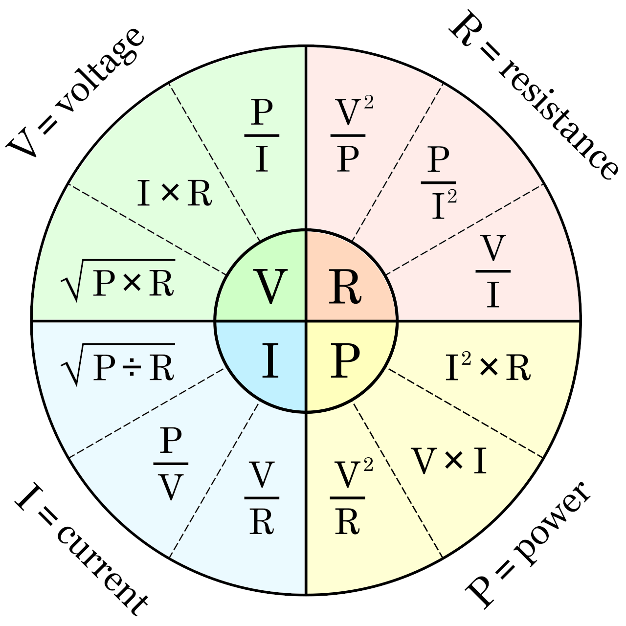
For example, if you need to understand the current (\(I\)), and you only have power (\(P\)) and resistance (\(R\)), you can use \(\sqrt{P/R}\).
This one simple thing will carry you very far in electronics.
Ohmic Material
Materials which obey Ohm's Law are called ohmic material. This includes wires, resistors, and other things. Not everything follows Ohm's Law, and in this case the current is not proportional to the voltage. These are called non-linear or non-ohmic materials/components. Diodes, semiconductors, and even the lowly fluorescent lamp, are non-ohmic components.
While Ohm’s Law states that resistance is a linear function, this rule is not universal and is in fact empirical. It is actually a linearized model of trillions or more of atomic (and quantum) scale interactions within a material, and it turns out that on average, the aggregated behavior looks roughly linear. This is a recurring theme, but you can also completely ignore this nearly all the time.
Series and Parallel Circuits
The two fundamental arrangements of components in circuits is series and parallel. These are composed to form more complex circuits, but fundamentally, these are the two to understand. To start, we're going to just talk about resistance circuits, but after, I'll discuss how resistance, capacitance and inductance are calculated for similar patterns.
Let's start with a series circuit. This is just a bunch of components in a line:
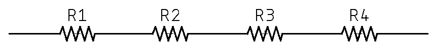
A series circuit’s defining characteristic is that all components in a series circuit have the same current flowing through them, which is why it is sometimes called a "current-coupled" circuit. Current can only flow in a single direction.
A parallel circuit is different:
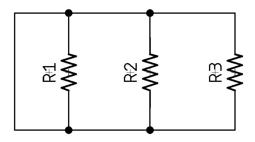
This can also be called a "voltage-coupled" circuit because there are multiple paths for current to flow, but the voltage will be the same across all paths.
So, how do you calculate the effective resistance, or capacitance, or ... well, it's pretty simple:
| Component | Series | Parallel |
|---|---|---|
| Resistors | \(R_1 + R_2 + \cdots+ R_n\) | \(1\over{{1\over{R_1}}+{1\over{R_2}}+\cdots+{1\over{R_n}}}\) |
| Capacitors | \(1\over{{1\over{C_1}}+{1\over{C_2}}+\cdots+{1\over{C_n}}}\) | \(C_1 + C_2 +\cdots+ C_n\) |
| Inductors | \(L_1 + L_2 +\cdots+ L_n\) | \(1\over{{1\over{L_1}}+{1\over{L_2}}+\cdots+{1\over{L_n}}}\) |
Note that one of the most common situations is to use 2 resistors, and so the equation can be simplified to:
This, of course, works for 2 capacitors as well when they're in series. Also, if two inductors are located within one another's magnetic fields, mutual inductance changes this calculation. See this article for more information.
Curious Similarities
It's worth thinking about 1) why resistors and capacitors's behaviors are reversed; 2) why resistors and inductors aren't.
Kirchoff's Laws
Kirchoff, smirshoff, am I right?
Seriously, though, there are two laws from Gustav Kirchhoff (around 1845), which, on the surface, seem 100% totally boring and predictable, but it's worth thinking a bit more deeply about them. Kirchhoff used Georg Ohm ‘s work as a foundation to create Kirchhoff’s current law (KCL) and Kirchhoff’s voltage law (KVL) in 1845. These can be derived from Maxwell’s Equations, which came 16-17 years later. Before we do that, though, we should briefly discuss, in a radically simplified form, the lumped-element model.
The model allows us to simplify a circuit into a series of nodes and connections (think graph theory) which we can simplify and down to a series of nodes that exhibit idealized attributes (resistance, capacitance, inductance, etc.). These nodes are joined by perfectly conductive wires. That's all, at its core, the model is. There's a lot of math, and proofs, and such, but you don't need to care almost ever.
When You Might Care
There are a few times where things might not be as simple as explained above. A good example is that a wire-wound resistor exhibits not just idealized resistance, but also inductance. In the lumped element model, we can represent that as a resistor and inductor in series.
Another example is when you're dealing AC circuits, though typically only high-frequency ones. In addition, it can fall apart when you have an electrical field between two distinct parts/nodes. For example, if you have two wires closely placed, they can become capacitively coupled.
Kirchhoff's Current Law
The algebraic sum of all currents entering and exiting a node must be equal.
Kirschhoff wrote this as:
or more simply:
Or \(\sum_{n}{I_n}\) if you want to be ffancy.
This was the first law that he proposed and describes how a charge enters and leaves a junction point or node. Take, for example, this circuit:
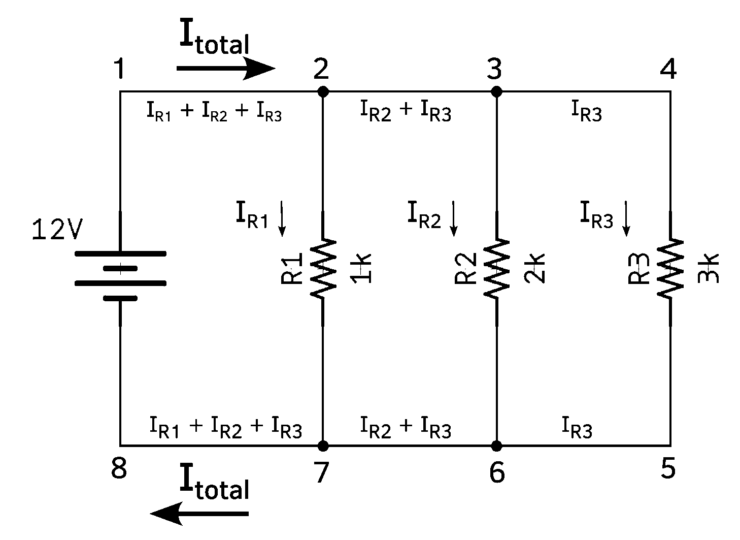
Here I'm showing that the total current (Itotal) is is present both between 1-2 and 7-8, but IR1 passes through R1, leaving only IR2 + IR3 passing between 2-3 and 7-6, etc. On the surface, this seems super obvious, and that's true, but it can help you analyze a circuit to understand current flows. For example, if we want to look at what's happening at node 6 in the diagram above.
First, we know that it is composed of IR2 + IR3, so we can solve:
Now, we can use Ohm's Law to figure out what IR2 and IR3 are:
$$\begin{aligned} I_{R2} &= {V\over R}\[5pt] &= {12\over 2000}\[5pt] &= 0.006 = 6\mathrm{mA}\[10pt]
I_{R3} &= {12\over 3000}\[5pt] &= 0.004 = 4\mathrm{mA} \end{aligned}$$
Finally, we can solve for I:
The negative sign on the -0.010 tells us that the current is exiting that node, rather than entering.
Kirchhoff's Voltage Law
The algebraic sum of all voltages in a loop must equal zero.
You can get fancy and write this as \(\sum_{n}{V_n}\), but you get the idea.
Like Kirchhoff's current law, this seems very simple on the surface, but it's also very powerful to use in analyzing a circuit. We are going to take a look at a simplified series circuit and see how this works.
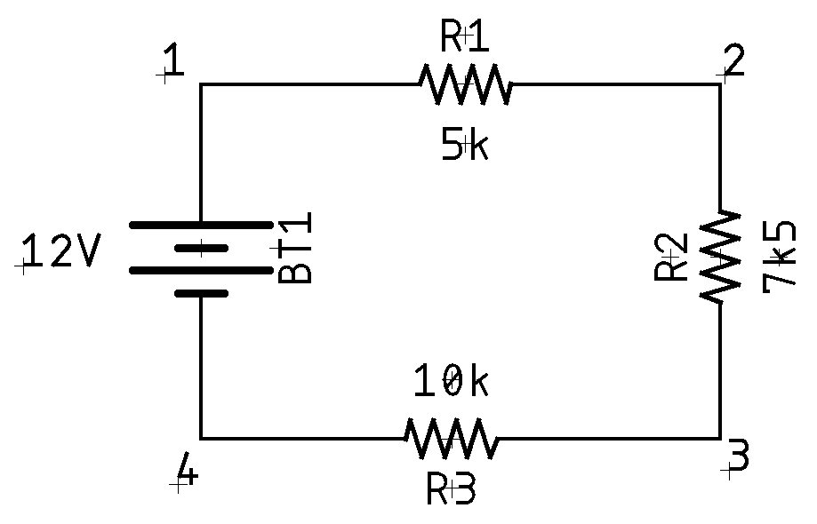
If we were to use a multimeter to check the voltage between points 4 and 1, putting the positive lead on 1 and the negative on 4, we would read 12V. We can use that as \(E_{1-4}=+12\). This is a good time to remind you that voltage is always relative. It is measured across something. So in the case of \(E_{1-4}\) we are talking about the voltage at 1 in relation to 4. If we continue around the circuit doing similar measurements we find:
| Measurement Location | Value |
|---|---|
| 1-2 | \(-2.\overline{666}\) |
| 2-3 | \(-4.0\) |
| 3-4 | \(-5.\overline{333}\) |
| 4-1 | \(+12.0\) |
If we sum these together:
Ta'da!
Voltage Divider Rule
An outgrowth of Kirchhoff's voltage law is the voltage divider rule. This means that in a series connection, the current is the same through each component. Thus, the voltage drops in a series connection must be proportional to the size of the resistances. The larger the resistor, the larger its voltage, and the larger its share of the total voltage. Thus, the voltage across any resistor must equal the net supplied voltage times the ratio of the resistor of interest (\(R_x\)) to the total resistance:
This is just a combination of two Ohm's law calculations into a single simplified formula. The resistor of interest (\(R_x\)) doesn't have to be a single resistor. It can easily be the sum of multiple resistors in series. The VDR is not required for any particular analysis. However, it it saves some time because it skips over dealing with current, and second, it demonstrates the ideal of a proportionality of voltage in a series connection. For example, if there are two resistors in series and one of them is twice the size of the other, then the larger resistor sees twice the voltage of the smaller resistor.
Comments or Questions?
If you have any comments, questions, or topics you'd like to see covered, please feel free to either reach out to me on Mastodon (link below) or open an issue on Github.