Precision Current and Voltage Signal Generator
Limitations
This is just what I know from experience. I don't know all the characteristics, and the documentation is nearly zero. It is only the quality of the output that made it worth looking at this in the first place. If you find mistakes or have other information, please let me know!
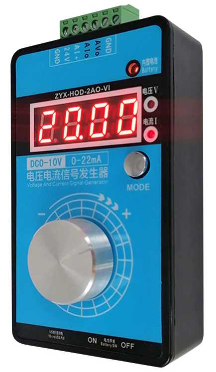
A while back, I picked up this voltage and current reference from AliExpress. It has a product number, I think of ZYX-HOD-2AO-VI, but who knows? I can't remember which person had mentioned it to me, but they thought it had excellent characteristics, and behavior far in excess of what you might expect for a sub $15.00 device. It's also quite compact at 3.9" (100mm) by 2.36" (60mm) by 1" (25mm).
One thing it didn't have, though, was a good manual, so I've pulled this together from both it's kinda "manual", some digging, probing, and general beating my head against the wall.
Let's start with the specs:
| Attribute | Range | Tolerance |
|---|---|---|
| Voltage range | 0-10VDC | 0.01V |
| Current rage | 0.22mA | 0.01mA |
| Load equivalence | 500Ω |
The one I bought has a built-in 3.6V LiIon battery that can be charged over a micro-USB connector. The screw terminal lock is also removable, something they don't typically mention. This means you can potentially swap them quickly for various setups.
Inside the Box
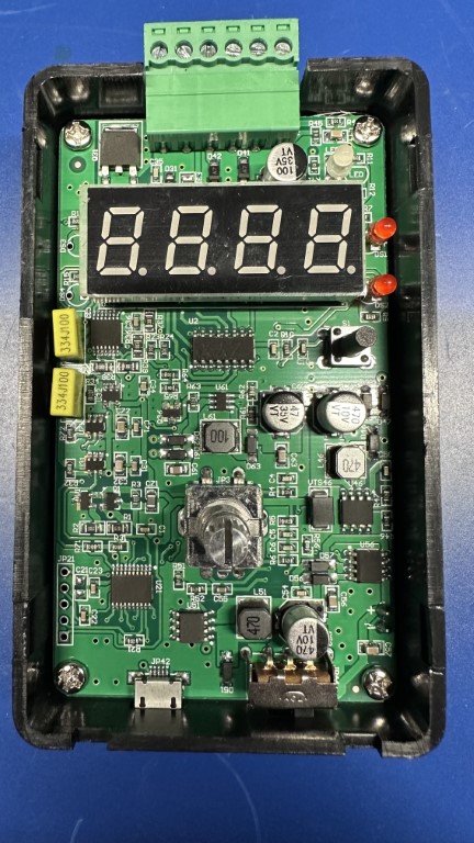
As I mentioned above, this device is far more complicated than anything at this price point has a right to be. If you pop the front cover off after removing the rotary knob, you peer inside, and find this.
That's a lot for what this does. Unfortunately, they've scrubbed all the ICs of any marks. There's one inside that has the faint residual marking of "ZYX", but that's useless. There's a few seemingly high-quality polyester caps as well (marked 334J100 on top). Still, impressive for the price, and explains the rather outstanding performance.
We truly live in a bizarre, and in many ways golden, era of electronics.
Power Options
There are three ways to power the one I have:
- External 15-30VDC power supply, which it will never draw more than 1W operating, and 5W charging.
- External micro-USB at 5V and 0.2A operating and 1A charging.
- Internal 3.7V battery.
Obviously, you can only use one of these at a time.
Output Modes
There are two output modes, current and voltage, which you can think of a constant-current and constant-voltage sources. You can switch between them using the MODE button.
Terminal Block
On the top of the device, there is a (removable) screw terminal bock. It has 6 connections, which are numbered left to right 1-6:
| Terminal | Label | Use |
|---|---|---|
| 1 | GND | Ground for either signal output or external 24VDC power supply |
| 2 | 24V | 24VDC positive connection for external power supply |
| 3 | AI+ | Not sure of this one, it discusses a two-wire acquisition device, but this isn't a 4-wire device. |
| 4 | AIo | Constant current output |
| 5 | AVo | Constant voltage output |
| 6 | GND | Ground for either signal output or external 24VDC power supply |
Changing Parameters
Getting to the parameters setting is a bit weird. First, there are settings for each mode (voltage v current), so you will need to make sure you're in the right mode before starting. To get access:
- Press and hold down the control knob for 2 seconds. This will display
F001, which is a reference to parameter 001. - Rotate the knob clockwise to select
F002. The first time you do this, you will get a display consisting of 4 underlines:_ _ _ _. This means that the device wants a passcode. - To enter the password you rotate the knob clockwise for a
|-symbol or counterclockwise for a-. To get to parameters F002-F009, you use the passcode|- - - |-. That's clockwise, counter-clockwise, counter-clockwise, clockwise. Then press down on the rotary control. To get to F100-F109, you will use a different passcode, which is|- - |- -, or clockwise, counter-clockwise, clockwise, and counter-clockwise. Again, press down on the rotary control. - Rotate the the parameter you want to change, then press down on the knob.
After you've set a parameter, or once you've not interacted with it for 10 seconds, it will return to "normal" operation.
| Parameter | Use (I) | Use (V) | Notes | Default |
|---|---|---|---|---|
| F001 | Coarse/Fine | Same | 0 = coarse, 1 = fine, 2 = quick output (F100 set above 0) | 0 |
| F002 | Display Range | Same | 0 = 20mA/10V, 1 = 20mA/5V, 2 = 22mA/3.3V | 0 |
| F003 | Actual v Percentage | Same | 0 = Actual I/V, 1 = Percentage of range | 0 |
| F004 | Coarse Adjustment Step | Same | See below | 1 |
| F005 | Fine Adjustment Step | Same | See below | 1 |
| F006 | Unused | Unused | ||
| F007 | 0.2mA Calibration Value | 0.1V Calibration Value | Allows you to adjust the actual output at 0.2mA or 0.1V | |
| F008 | 20mA Calibration Value | 10V Calibration Value | Allows you to adjust the actual output at 20mA or 10V | |
| F009 | Screen Brightness | Same | 0 = normal, 1 = bright, 2 = super bright | |
| F100 | Quick Output Mode | Same | 0 = disabled, 2 = 9 distinct points (F101-F109) | |
| F101 | Quick Output Value #1 | Same | ||
| F102 | Quick Output Value #2 | Same | ||
| F103 | Quick Output Value #3 | Same | ||
| F104 | Quick Output Value #4 | Same | ||
| F105 | Quick Output Value #5 | Same | ||
| F106 | Quick Output Value #6 | Same | ||
| F107 | Quick Output Value #7 | Same | ||
| F108 | Quick Output Value #8 | Same | ||
| F109 | Quick Output Value #9 | Same |
Quick Output Mode
It is possible to set "preset" voltage and current settings, but no matter what I try, I cannot figure out how to access them after they have been set. If you know, please let me know!
Adjustment Steps
Out-of-the-box, the unit does voltage steps in 0.1V increments, and current in 0.1mA steps. This can be adjusted using the parameters F004 and F005 mentioned above. For both, the coarse adjustment steps controls how many tenths (0.10) each click of the rotary knob increases things. I have yet to figure out how F005 works, actually. It seems to imply that it might be adjusting at the hundredths, but that just doesn't seem to be the case.
Saving Values
If you want to set a "default" value for it to start up in, you can
short-press the rotary wheel (about 1s). When you do that, it will
display . . . . on the screen, which means it saved the value. Now,
when you turn the box back on, it will use that as the starting point.
Precision
I took the following measurements with a B&K Precision 2709B multimeter, but it should be good enough for hobbyist uses. Here's a few checks at a few points out-of-the-box, and before any calibration was done. I didn't do calibration as I don't currently own anything I trust more.
| Voltage Set | Voltage Read | Δ V | % |
|---|---|---|---|
| 1.3 | 1.297 | 0.003 | 0.023 |
| 3.3 | 3.296 | 0.004 | 0.013 |
| 5 | 4.995 | 0.005 | 0.01 |
| 9 | 9.001 | 0.001 | 0.01 |
| 10 | 10.002 | 0.002 | 0.02 |
Calibration can be done using F007 and F008 in both current and voltage mode.
Mechanism of Operation
Honestly, not being able to see the labels on the chips makes it super hard to figure out how this thing works. Reverse engineering hardware isn't my expertise. But from reading a bit between the lines, I'm pretty sure it's a DAC-controlled constant voltage and current source. You can read more about how this might work. This would also explain why the current delivery is so low. Given the apparent 0.01V and 0.01mA precision, I would guess that it's driving it with a 12-bit DAC, which are relatively inexpensive at this point (under $1.00 in any quantity).
Comments or Questions?
If you have any comments, questions, or topics you'd like to see covered, please feel free to either reach out to me on Mastodon (link below) or open an issue on Github.