Using Calipers and Micrometers
Storage of Calipers and Micrometers
 One thing I want to emphasize here from the start is that these are
precision tools, even the inexpensive ones, and care for them is
critical. I strongly recommend only storing them in the case they came
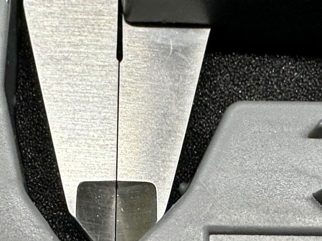
in, and ensuring that when you close them to put them away, you leave
a tiny little gap so that the anvils (faces) of the measuring surfaces
are not touching. It doesn't have to be much, but it should be at
least 0.1mm. When they're slightly apart, twist the locking screw to
keep them in place. In the photo, you can see that they are almost
but not quite touching.
One thing I want to emphasize here from the start is that these are
precision tools, even the inexpensive ones, and care for them is
critical. I strongly recommend only storing them in the case they came
in, and ensuring that when you close them to put them away, you leave
a tiny little gap so that the anvils (faces) of the measuring surfaces
are not touching. It doesn't have to be much, but it should be at
least 0.1mm. When they're slightly apart, twist the locking screw to
keep them in place. In the photo, you can see that they are almost
but not quite touching.
Why does this matter, you might wonder? Because the environment, primarily. All materials expand or contract with their temperature and other conditions. If the face of the measuring surfaces are in full contact, and then you tighten the locking screw, there are forces at work when the two sides expand and contract differently, which can lead to damage, minute warming, or other things that will reduce the accuracy of the device. It really doesn't take much.
Using Calipers
Calipers are the workhorse of the measurement world. More than anything, they will give you a reasonably accurance understanding of what you're dealing with, quickly, and with minimal fuss. For the purposes of this discussion, I'm going to be talking purely about digital calipers as that's what most entry-level calipers are. They also have the advantage of being able to read out in both metric and customary units, which is not the case with dial and vernier calipers.
Parts of a Caliper
Let's dig into the various parts of a set of calipers and how to use them. We will start with a diagram of all the pieces on the Clockwise digital caliper that I use most of the time. Others will be slightly different, but will generally follow the same design.
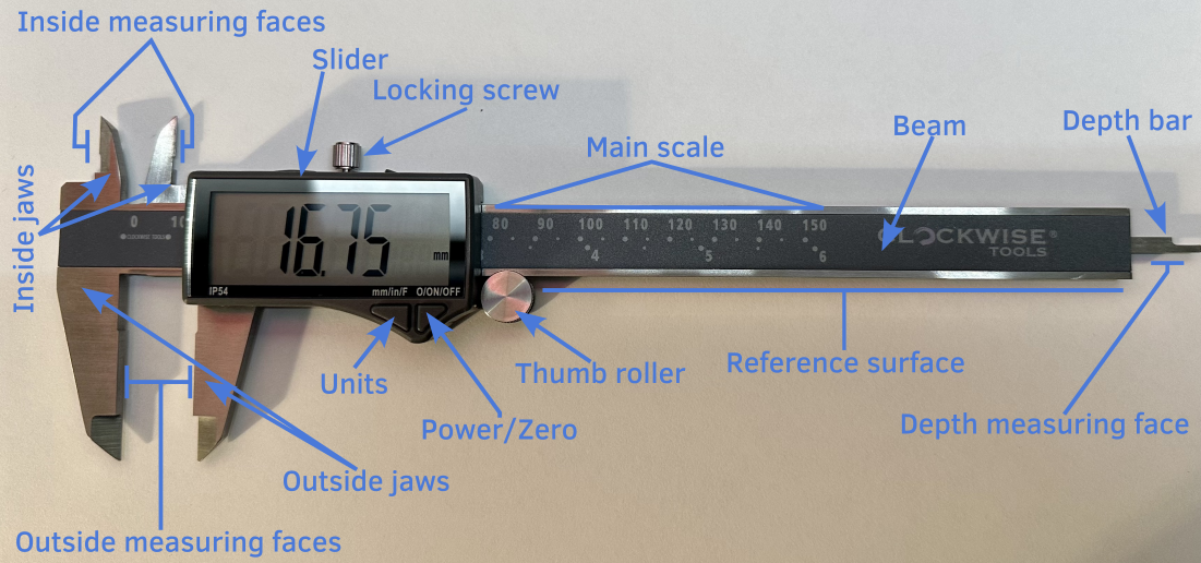
- Beam
- The beam is the main material piece of the caliper upon which everything else rides. The precision and accuracy by which this is manufactured will determine the overall accuracy and precision you can achieve with the tool. More expensive tools are simply manufactuered to much higher standards, and sometimes with much more expensive (and reliable) materials. When a caliper is said to be 150mm, it means that the beam is designed for up to 150mm measurements. Everything else is on the beam in some fashion.
- On the beam, you will find printed the main scale. This is the overall dimensions of the caliper. In addition, along the sides you will find a reference surface. This is used during the calibration of the caliper and is, in better calipers, has a lapped finish to mirror levels to achieve near perfect flatness.
- Slider
- The slider is the component that is moving along the beam, and contains the measurement display as well as a few other things. First, it contains a locking screw, which is used to hold the slider in place, especially during storage (see headnote). It also contains the power/zero button which can be used to zero the caliper or set the origin (see below). Finally, for most digital calipers, there is a units button of some sort that allows it to change from millimeters to decimal inches, and potentially fractional inches. If you want to take a measurement in both, I strongly recommend tightening the locking screw before pressing any button to ensure that you get an accurate and consistent measurement.
- Thumb Roller
- The thumb roller is used to bring a caliper into contact with the surface you are attempting to measure. You should never slam the jaws into the surface, but instead bring them close, then slowly ease into the surface using the thumb roller. This will ensure that you do not apply too much pressure, and typically will get a much more consistent measurement.
- Jaws
- The jaws are hold the measuring faces (below), and are what moves to allow for different measurements.
- Measuring faces
- There are two different measuring faces on a set of calipers, depending on what you are attempting to measure. If you are measuring the outside of something (think outside diameter of a pipe), you would use the outside measuring faces. For measuring the inside of things (again, think inside diameter of a pipe), you use the inside measuring faces. In the section below on use, I'll talk a bit more about how exactly to use them.
- Depth bar and measuring surface
- Sometimes, you want to measure the depth of something; a hole, for example. To do this, you can use the little bit at the end that extends called the depth bar, and the depth measuring surface. By sticking this in a hole, you can identify the real depth of the hole. For the longest time, I didn't understand the odd shape of the depth bar, but this question and answer on Stack Overflow provides a clear explanation with diagrams, and it's worth a read.
Setting the Origin
Before using your calipers, you need to ensure the origin is correct. To do this, clean the blades with a soft cloth to make sure they're clean (even small amounts of dust can imapct measurement accuracy). Then you can close the jaws (carefully, don't slam them) using the thumb roller. It should read 0.0mm, but if it doesn't make sure they're clean, and then you can press the zero/origin button to set the origin.
More Expensive Calipers
On higher-end calipers, the origin is set at the factory, and there should never be a need to set it. It may only need to be set when the battery is changed on the calipers, but otherwise it will stay in correct alignment. This is one way the pricier models differ. It's a couple seconds, but it can add up.
Relative Measurement
There are occasions, especially in machining, where you are attepting to understand the difference between where you are and where you want to be. For example, if you are turning a piece of metal on a lathe, and you want it to be 17mm exactly, you can set the calipers to 17mm (ideally using gauge blocks), and then zeroing them on this point. On more expensive calipers, there's typically a "relative" button that you use for this. Then, as you measure something, it will tell you exactly the delta between where you want to be and where you are. You can easily see that you need to take X amount off and ease into the correct dimensions.
The zero function is also useful when trying to decide two things will fit together. What if you want to know if a shaft will fit into a hole? You could measure one, then the other and do a bit of math to get the clearance (or lack thereof). With calipers? Measure the shaft, click zero, then measure the hole. The value on the screen is the clearance (or not).
Taking Measurements
So, after doing all of that, you are ready to take some measurements. I know it seems like a lot, but following a habit of cleaning and zeroing your calipers every time you use them will result in a more reproducible measurement. Let's say we want to take the outer, inner, and depth measurements of a cylinder.
Outer Diameter
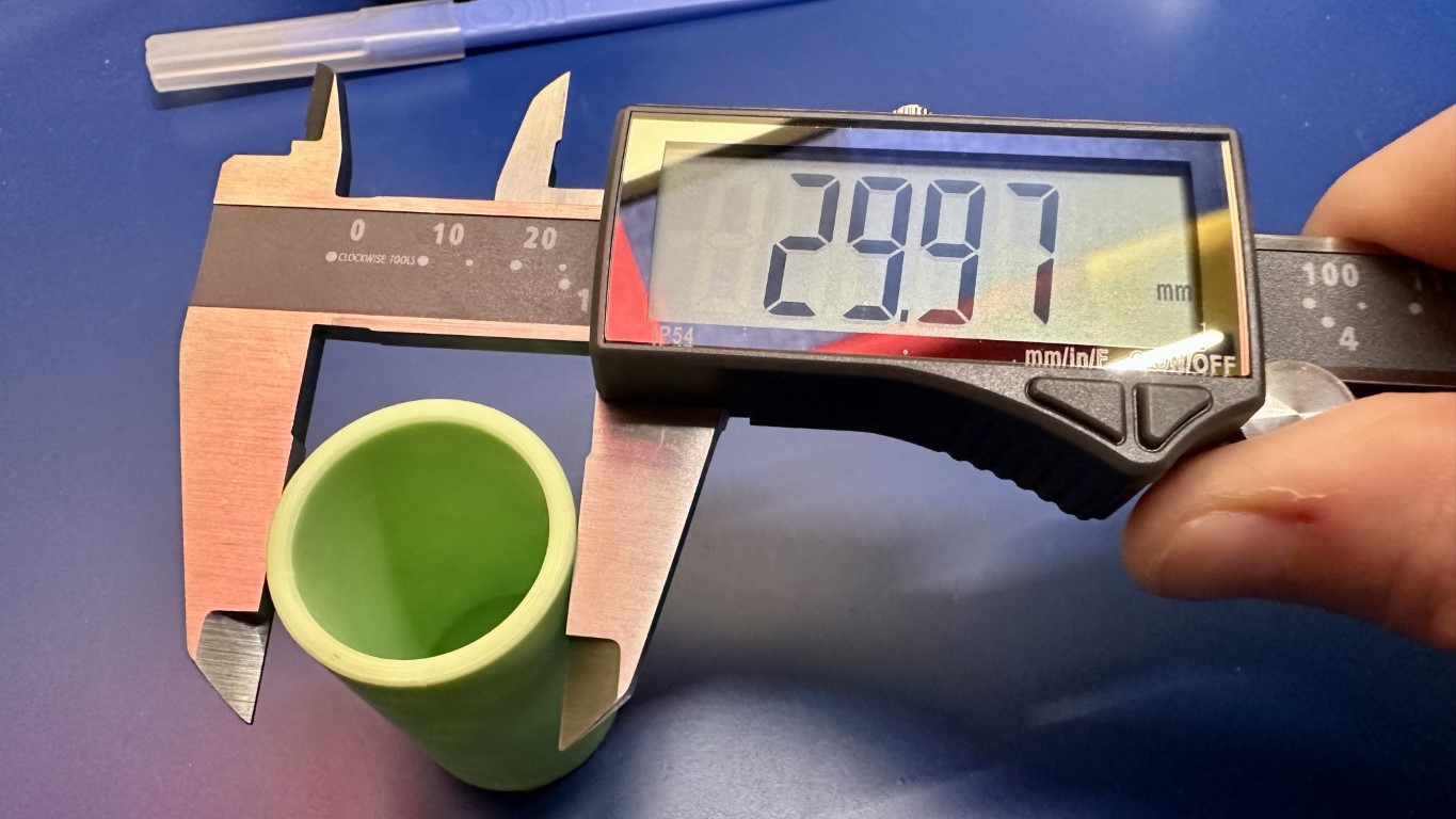
If we look at this photo, we can see the cylinder is placed within the main part of the measurement surface, and not only at the tips. While there are occasionally reasons to use the tips, typically you want to use the main part of the surface if at all possible. From this we can read the measurement: 29.97mm
Now, since this was a 3d printed part, and we know that accuracy and consistency are not the halmarks of FFF printing, let's take a second one:
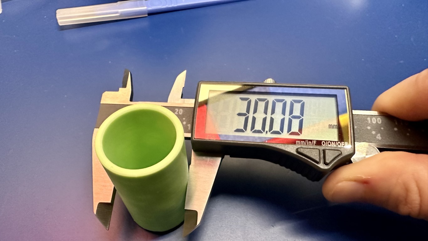
Ah, see, the second measurement is 30.08mm, or 0.11mm different. Not gigantic, but when working with tolerances and fitting things together, this can be a big deal. I strong recommend taking several measurements along the length of a surface. For what it's worth, this was printed from a model where it was 30mm exactly.
Inner Diameter
Now, let's take a look at the inside diameter of the cylinder:
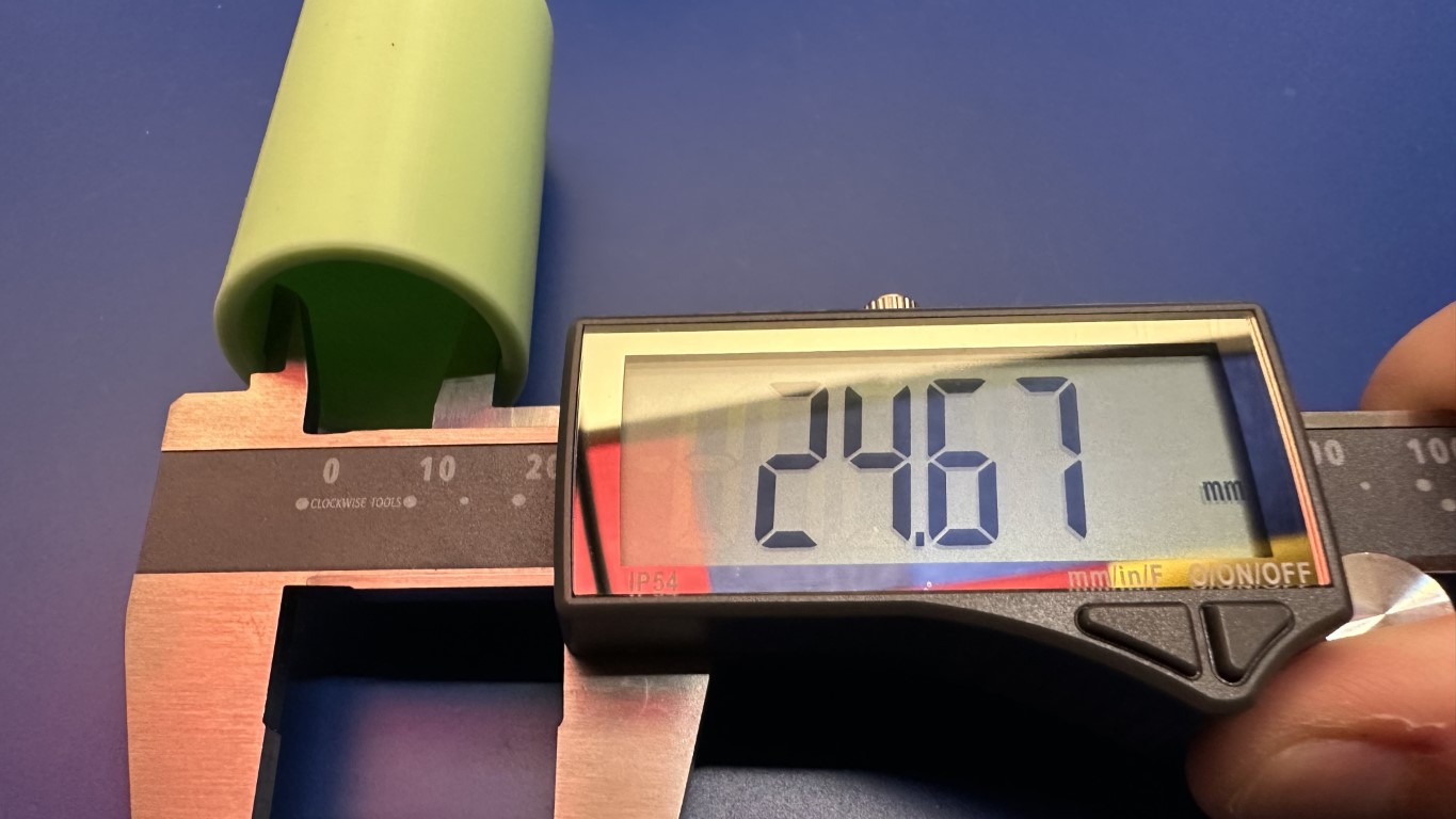
Here we can see that the inside diameter is 24.67mm, which is a little off since the wall thickness was supposed to be 5mm, and therfore it should have been 25mm. Still, it's kinda close? There's a lot to talk about with getting accurate prints, and I hope to address that sometime soon over in the section on 3D techniques.
Depth Measurement
Finally, let's see just how deep this cylinder is. This is often done for screw holes, and similar things. For this, we will use the depth bar, and rest the face of the beam on the top of the cylinder, like so:
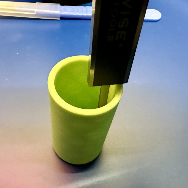
As mentioned above, there's some technique that you can read about here. This isn't a super intuitive way to hold an object, so you'll want to practice it a few times so that you can get smooth movement without needing 7 hands.
Battery Life
Like all electronic things, a digital capiler requires power to function. You should, however, expect a battery in the calipers to last at least a few years, even when being used regularly. Mine, for example, are approximately 5 years old, and still have the original battery in them. When it comes time to replace, most calipers use either a LR44/SR44 or CR2032 for power.
Other Features
One thing you might find in higher-end calipers (or even the Clocwise ones I use) is a digital output that provides readings to a computer. There's a few formats for this, and you should look into what your caliper uses, but the main use for this is in a metrology situation where you are taking repeated measurements, and you need to record all the results automatically.
Tips on Measuring Specific Things
More to Come
I'm hoping to do some pictures and examples of how to measure a few things that can be trick. Connectors,
Using Micrometers
More to Come
This will be filled in in the future.
Comments or Questions?
If you have any comments, questions, or topics you'd like to see covered, please feel free to either reach out to me on Mastodon (link below) or open an issue on Github.