Parameters in Parametric Models
Naming Scheme
Something I've learned the hard way is that you need to have a naming scheme when you start to do a lot of parameters in your models. Otherwise, you end up finding it difficult to identify which parameter you're looking for. Parameters in Fusion360 can have alphanumeric characters and the following special characters:
_Underscore"Double Quote$Dollar symbol°Degree symbolµMicro symbol
They cannot have a space, so I typically use PascalCase. This is the scheme I use:
| Name | Use |
|---|---|
*ID |
Inside Diameter of a circle-like thing. |
*OD |
Outside Diameter of a circle-like thing. |
*Depth |
The depth of a hole |
*Clearance |
Any specific clearance that you need to think about. Note this is different than fit (see below). |
*Count |
Number of something (e.g., holes) in a surface or body. |
In addition, I always create the following three parameters to allow for modeling of various types of fit if something is going to be 3D printed.
| Name | Use |
|---|---|
| ClearanceFit | Allowance for a clearance fit. |
| TransitionFit | Allowance for a transition fit. |
| InterferenceFit | Allowance for an interference fit. |
Calculations
Starting with the May 2023 release of Fusion360, you can now use conditional operations in your parameters. This is covered in the reference. This opens up a huge new arena for exploration. For example, you could do something (simplified) like this for the number of holes in a hub:
HoleCount = if(HubOD >= 100mm; 7; 5)
This would set the HoleCount to 7 if the HubOD (hub outer diameter) is
greater than or equal to 100mm. You can also chain them together:
HoleCount = if(HubOD >= 100mm; if(HubOD >= 200mm; 9; 7); 5)
Future Enhancement
In the future, I'll probably combine the parameters
for various types of fit with the new if function, and add a PrintQuality
that will allow setting the PrintQuality variable to then calculate the actual
fits.
Default User Parameters
Global Parameters
Currently, Fusion360 doesn't have a concept of global parameters that you can set for everything. This would be awesome to have in this case, but not yet. There are ways to fake it, but I find them overly complicated, and the CSV file with Parameters I/O is a much simpler solution.
One of the most powerful things with a parametric modeling tool is being able to create standard parameters that drive the model. Often, a lot of these are references to external parts that you need to interact with, like a screw. To simplify my life, I have put together a CSV that contains:
- Fits for my printer: interference, transitional, and clearance.
- Standard metric screws for M2 - M12 in all the default standard threads. This is for socket head screws, which are my go-to. The insert and tap information will work for any metric screw of that size and thread pitch (yay metric!). These are all just "standard" thread pitches.
- Sizes for threaded inserts.
You can download the CSV from here: f360_default_parameters.csv
You can import them quickly with the Parameters I/O add-on that Autodesk provides (you'll need to install for some weird reason). Once imported, if you look at user parameters, you'll see something like this:
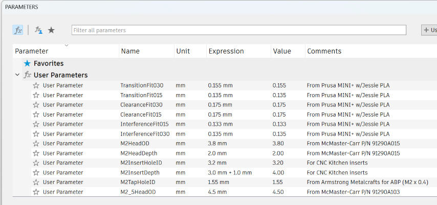
The naming is based on this pattern:
<type of fit>Fit<layer height without decimal>for the various fits.<size>Head<OD/Depth>for the outside diameter (OD) and depth (height) of the screw.<size>InsertHoleIDfor the inside diameter (ID) of the hole you'll need to insert the insert.<size>InsertDepthfor the depth of the insert when you do an extrude cut. Note there are also someInsertShortDepthfor the CNC Kitchen short inserts.<size>TapeHoleIDfor the ID of the hole you'll need if you plan on tapping the holes.<size><fit>ClearanceHoleIDfor the clearance holes as specified in Machinery's Handbook in their normal, close, and loose fits.
I've provided references to where the data came from originally (for example, the McMaster-Carr screw part numbers). There's a few things you might need to do:
- You should update the fits for your printer. This is just for my Prusa MINI+, and won't necessarily match yours. It's a good start if you don't want to fuss about it, although many cheap 3D printers have much bigger tolerances.
- When you want to use
M3HeadOD(for example), you'll want to allow for tolerance. I typically useTransitionFit030, which will get a snug fit that doesn't drag when you put the screw in. To do that, when you create the circle, just set the size toM3HeadOD + TransitionFit030. I didn't include the fit in the main size because different people want different fits in different situations.
Comments or Questions?
If you have any comments, questions, or topics you'd like to see covered, please feel free to either reach out to me on Mastodon (link below) or open an issue on Github.