Filters
RC Filters
RC filters, so named because they use a resistor (R) and capacitor (C) are a super easy way to construct a filter. They don't necessarily have the best performance under all circumstances, but they're often a great starting point when working through an idea.
Low-Pass
For a low-pass filter, where we only allow frequencies below the design point, we can construct it like this:
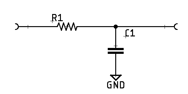
We can then calculate the cutoff frequency (\(f_c\)), which is a -3 dB or 70.7% reduction for the filter:
But if you know the frequency (\(f_c\)) you want to achieve, then you can use either of these two to figure out the capacitor (\(C\)) or resistor (\(R\)) you need:
In fact, we can play with the circuit here. You can adjust the resistance (R) and capacitance (C) of the low-pass filter while a signal sweep runs from 100-1,000Hz.
High-Pass
For a high-pass version of the RC filter, we simply flip the arrangement of the resistor and capacitor, and can use the same equations to calculate the \(f_c\) cutoff frequency. Similar to the simulation above, we can take a look at the high-pass version here:
Pi Filters
A Pi filter is a type of filter constructed with 3 elements rather than the traditional two-element passive filter. Since the constructed arrangement of all the components creates something that looks like the Greek letter Pi (\(\pi\)), the name Pi filter is used. Pi filters are pretty easy to calculate and design, and if needed, you can often buy off-the-shelf pre-configured ones for very cheap.
Pi filters have a few advantages over simpler LC filters:
- Can handle very high voltage across the filter, which makes it suitable for high voltage DC applications.
- Low ripple. When used in a DC filtration purpose, it's very effective and leaves very little ripple behind in the output.
- Easy to use for high-frequency applications.
Their disadvantages are mostly around cost:
- High wattage inductors are required in power situations. High wattage inductors are pricey.
- High value input capacitor. This can create space constraints and also increase cost.
- Poor voltage regulation in situations where the load is fluctuating constantly
Low-Pass
A low-pass filter only allows frequencies below its design point to pass. The design of a low-pass Pi filter is pretty simple. The circuit consists of two capacitors connected in parallel with an inductor in series which forms the Pi shape as shown below:
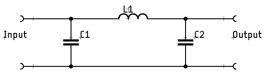
We can find the -3dB point of a low-pass filter using this equation:
High Pass
Reversed from a low-pass filter, a high-pass filter only allows frequencies above its design point to pass. A high-pass filter has just a flipped design with the the inductors in parallel and the capacitor in series:
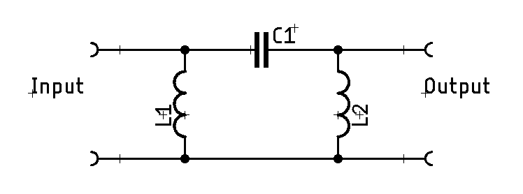
It's -3dB point can be calculated exactly the same.
Comments or Questions?
If you have any comments, questions, or topics you'd like to see covered, please feel free to either reach out to me on Mastodon (link below) or open an issue on Github.