Reference Designators
Unoriginal Thoughts
None of this is original work, and the main reason I have put this here is that, unfortunately, the standards that govern this are expensive and therefore not easily available.1
When designing a schematic, or PCB, every component needs a unique identifier. This is called the reference designator. You've seen these. They're designations like C12, R44, Q1, or U4. They're not just line noise or random things, but encode meaning into them as well. There are two main standards that govern this:
- ASME Y14.44-2008
- IEEE 315-1975 (yes, 1975)
We'll break this apart into the "class" designation, which is the letter prefix, and the numbers after.
Class Letters

The class letters you see in schematics (R12, C33) are all derived from a specific standard that is, by and large, global. In the United States, this is standardized as IEEE 315-1975 (ANSI Y32.2-1975), "Graphic Symbols for Electrical and Electronics Diagrams (including Reference Designation Letters)". This is 264 pages, but most of it is focused on the actual symbology of all sorts of things, and far more than just what we might concern ourselves with, such as the one to the right for an explosive squib (igniter). Specifically, §22, "Class Designation Letters" covers the actual letters used.
There are many possible uses for each of these, but I've tried to just collate the most common usages I've seen.
| Letter | Usage |
|---|---|
| A | General circuit element Sensor |
| AR | Amplifier |
| AT | Bolometer Termination |
| B | Blower |
| BT | Battery |
| C | Capacitor |
| CB | Circuit breaker |
| CP | Connector adapter |
| D | Diode Photodiode Thyristor |
| DL | Delay line |
| DS | Display |
| E | Antenna Electrical contact Ferrite bead Magnetic core Permanent magnet |
| F | Fuse |
| FL | Filter |
| G | Electronic chopper Generator Oscillator |
| H | Fastener (hardware) |
| J | Jack Connector receptacle (stationary) |
| K | Contactor Relay |
| L | Inductor Non-transformer coil |
| LS | Buzzer Speaker Siren |
| M | Clock Timer Instrument Meter |
| MK | Microphone |
| MT | Accelerometer Measuring transducer |
| P | Plug Connector movable portion |
| PS | Power supply |
| Q | Transistor Phototransistor Semiconductor switch |
| R | Resistor Rheostat Potentiometer Shunt |
| RT | Current-regulating resistor Thermistor |
| RV | Voltage-sensitive resistor |
| S | Contactor Switch |
| SR | Slip ring |
| SW | Switch (non-standard, but very common) |
| T | Transformer |
| TB | Terminal board/strip |
| TC | Thermocouple |
| TP | Test point |
| U | Integrated circuit Photocoupled isolator |
| V | Electron tubes |
| VR | Voltage regulator |
| W | Bus bar Cable Wire |
| X | Fuseholder Lampholder Socket Terminal strip |
| Y | Oscillator Quartz crystal |
| Z | Resonator |
Number Assignment
The general rules are:
- Start in the upper left of a schematic.
- Move left to right, top to bottom.
- Never re-use numbers.
- Always increment from the end.
What the standard says, specifically in §2.1.3:
Within each significant item (unit, assembly, subassembly, etc.), for the parts of each class, numbers shall be assigned sequentially on the schematic diagram in a systematic manner beginning with 1. Preferably start at the upper left of the schematic diagram and proceed from left to right and top to bottom for each successive portion of the circuit. Continue (preferably from left to right) until all parts of the circuit have been designated in order of input to output or functional sequence. If revisions require deletion or addition of items, the original items should not be renumbered to keep the series consecutive. Added items shall be assigned numbers following the highest number originally used. Numbers assigned to items that have been deleted shall not be reused.
For small projects, people will typically start with 1, and work their way up, as it's unlikely you'll have more than 100 of any one type of component (e.g., resistor). In commercial work, like a modern motherboard, you may see 3, or even 4-digit numbers. In addition, I have seen companies use a number scheme for a multi-board product that is:
<ref letter><board number><incremented number>
so you'll find resistor 33 on board 4 marked as R433.
Suffix Letters
If parts of a component are drawn separately from each other, it is normal to append a suffix letter to the designator. For example, if you had an IC which was a dual op-amp, and it was designated U3, you might draw them separately (for various clarity and style reasons) and label them as U3A and U3B.
Component-Specific Guidance
For many types of components, there is specific guidance for how to refer to various aspects of them. We're going to cover a few of the most common.
Terminals
For terminals, whether they be terminal blocks, relays, switches, where there are aa number of connections, you would append a dash and the number of the pin. For example, for a 3 position terminal block, designated X1, the individual contacts would be X1-1, X1-2, and X1-3.
Sockets
Sockets for other components are prefixed with the letter "X". So, for example, for U1, the socket is XU1.
Connectors
Connectors are broken into two pieces: the movable and the stationary component. The movable component is typically designated with a "P", where-as the more stationary one is designated with a "J" (or sometimes "X").
Relays
Oh no... relays are a mess. The problem is that there are very different ways to refer to the contacts on a relay. One, IEC 60947-1, another from the Relay and Switch Industry Association, and another other is the DIN system, specifically DIN 72552, which you'll see extensively in automotive applications.
I'll be honest. I just look it up every time I need it and I don't feel like I can make sense of it for you quite yet.
Large Systems
There's a ton in ASME Y14.44-2008 covering how to structure and organize components in a larger system. Specifically, §2.2, "Complete Reference Designations" talks about units, sub-assemblies, etc. and how to number and organize them. This is something I find very fascinating, and I'll likely discuss in another area eventually.
Just to give you a sneak peak, here is Figure 7 from that standard:
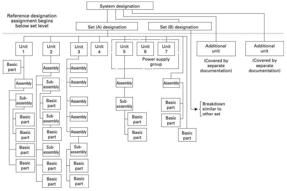
The short summary of it is that you break the designator down into three pieces:
- Unit number
- Subassembly class letter and number
- Item class and number
For example, the 12th capacitor in the first subassembly B of unit 1 would be written as: 1B1C12.
I'm not sure that's clear, but it is at least standardized. As I mentioned above, people often don't use this scheme and develop their own.
Tool Support
Any tool that does schematic capture, such as Fusion 360/EAGLE, KiCAD, Altium Designer, etc., will automatically deal with naming of things on the schematic, and almost always correctly according to the standard. Where you can run into problems is if you, like me, create a bunch of resistors, and then move them around, and now the numbering doesn't follow the left-to-right, top-to-bottom scheme.
If you use Fusion 360 or EAGLE, there is a ULP to renumber automatically. I'm sure that others have similar tools to renumber things for you. If you know of them, let me know at the link below.
Third-Party Resources
- ABB guide to relay nomenclature
- Indian (English) version of IEC 60947-1:2004
- Engineer's Relay Handbook (archived)
-
One might be able to find some of them for "reduced cost" if one were to use a search engine to find a specific file type PDF with the standard's number. Hypothetically. Alas, Carl Malamud hasn't gotten around to it yet. ↩
Comments or Questions?
If you have any comments, questions, or topics you'd like to see covered, please feel free to either reach out to me on Mastodon (link below) or open an issue on Github.