Protecting Circuits
What Can Damage a Circuit?
Before we talk about what kind damage a circuit, let's talk about the three major types of damage that a circuit can succumb to:
- Catastrophic damage. This is something that causes the component or circuit to fail completely. When people talk about "releasing the magic smoke", this is what they're talking about.
- Parametric damage. This is when the damage is not immediately obvious, but instead shows up as a change in one of the defining parameters of the component. For example, the ESR of a capacitor might change enormously after ESD damage.
- Latent damage. Here, like parametric failure, the damage can go unnoticed for some period of time. You can think of latent damage as a kind of stress on the component that, over time, builds up, till something small instigates a complete failure of the component.
So, what are some of the major causes of these? They break down into the following categories, typically:
- Environmental. This is the temperature, humidity, and presence of potential other materials, such as corrosive compounds.
- ESD. Electrostatic discharge is the result of the build-up of electrical charge, typically on the human body, that is then transferred very quickly to the component. Think about the experiment with a balloon and hair. What causes your hair to stand up is the electrostatic buildup on the balloon's surface. The voltages involved can easily be tens of thousands.
- Circuit behaviors. As we'll talk about later, sometimes there are behaviors in the design of the circuit that introduce unexpected electrical patterns in a component. These are different than ESD as they are coming from inside the circuit, rather than outside.
Electrostatic Discharge (ESD)
What Parts Can Be Damaged by ESD?
This is an area that is the most contentious with hobbyists versus professionals. While nearly every component can be damaged by ESD, the most likely victims are:
- Integrated circuits. ICs can sustain burnout (just what it sounds like), contact damages, or damage to the interface circuitry on the IC. For example, excessive current flow in ICs forms holes in chips. It can result in excessive heat generation, which may lead to damage or early failure to not just the IC, but other components in the spatial neighborhood.
- Transistors. ESD can cause insulation breakdown, thermal stress, metal deposition failure, or even the the migration of materials from one side to another.
- LEDs. Like other semiconductors above, LEDs can sustain damage from ESD. This takes the form of material loss in the substrate responsible for emission. More powerful LEDs often have ESD protection circuits on them, in the form, typically, of another diode.
- Capacitors. While we typically think only of semiconductors, both aluminum-electrolytic and ceramic capacitors can be damaged. The damage shows up as parametric damage typically, and more obvious as the voltage increases in circuit.
- Resistors. Thin and thick-film resistors are subject to ESD damage. This manifests itself as parametric damage that (typically) reduces the resistance. While minor, repeated exposure may cause it to exceed the tolerance specified.
How to Protect
While there are very extensive practices followed in production environments, the hobbyist really doesn't need to obsess over this. I would recommend a few simple rules:
- Use either a static-control mat or wrist-strap, or both.
- Store ICs, especially high-performance or low-voltage ones, in ESD safe packaging, either in the form of ESD containers (typically black) or dissipative foam (also black). Obviously foam isn't very effective without the leads of a DIP/etc.
- Touch something grounded when you first sit down. This can be the metal case of a bench power supply, or anything else which is grounded.
If you take those steps, you're highly unlikely to have any major mishaps. If you start selling things to other people, then you might want to up your ESD protection game.
Environmental
Environment shows up in a couple of different factors: temperature, humidity, chemicals, and finally what we'll call "build-up". Temperature changes can cause an electronic circuit to fail. This can show up in a couple of different ways though:
- Complete failure due to excessive overheating well outside the operating temperature range for the component.
- Sustained operation outside the operating range for the component.
- Physical thermal stresses due to rapid shifts in temperature.
Every component has a manufacturer-defined operating (and storage) temperature range. Over time, these have been grouped into a couple of de facto industry standards:
| Name | Lower (C) | Upper (C) | Swing (C) |
|---|---|---|---|
| Commercial | 0 | 70 | 70 |
| Industrial | -40 | 85 | 125 |
| Military | -55 | 125 | 180 |
As you can see, the variation is huge (2.5x), and along with that comes a wildly increasing cost. Above military is actually another (somewhat orthogonal rating) for "radiation hardened" components which are designed (primarily) for space applications. Where as a good LDO regulator in commercial (or even industrial) ratings might cost you $1-5 USD, the radiation hardened one will easily set you back $500-1,000 USD for a single part. They also come in some rather unorthodox packages.
But there's another way, even operating inside the designed range, you can have failures. Wih temperature swings, you will experience expansion and contraction of materials in the component and PCB. These expansions and contractions may cause a warped board and damage to solder joints.
Another equally devastating environmental factor is moisture, especially in the form of humidity.. If moisture is introduced to your electronic circuits, it can cause rust, oxidation, and corrosion rather quickly. This is why you're often see ratings for operating humidity (non-condensing).
Lastly, and one that people often overlook, is build-up. Build-up is the accumulation of material such as dirt, dust, fibers (human and otherwise), and even small insects and can also contribute to electronic circuit failure. This build-up over time can clog up fans thereby reducing air flow, or otherwise impede the head dissipation of ICs and heat sinks. This leads to overheating and electronic circuit failure.
Protection typically involves a few things:
- Understand the environment you're operating in.
- Account for the heat dissipation of things like ICs and resistors.
- Ensure adequate air flow, whether passive, convective, or fan-driven.
More airflow, especially with filtration, can also reduce the probability of settling of build-up onto components.
Circuit Behavior
More to Come
Will be talking about things like back (reverse) EMF, reverse polarity, et.c
Circuit problems come in a few major categories: isolation failure, over-current, and over-voltage.
Isolation
About the Name
Often just called isolation, galvanic isolation gets its name from Luigi Galvani a cotemporary of Alessandro Volta, also of the galvanic cell.
Galvanic isolation, electrical isolation, or just simply isolation, is a technique of separating different parts of a circuit so that there is no possibility of current flow (no conduction path). So, why might we want or need this. There are two main reasons:
- Safety. It is a good way to prevent the possibility of electrical shocks in systems that are dealing with high voltage or current.
- Separate grounds. Since ground is basically the universal return path, we have situations where we need to have different grounds which are at different potentials (approx. voltage).
It doesn't mean there's no way to communicate between the sections, it just means that it can't be a galvanic/electrical communication. This does leave us with a few major options:
- Inductive
- Capacitive
- Optical
The one we use largely depends on whether we are attempting to isolate power (current) or isolate a signal (tiny current).
Transformers
When attempting to provide isolation for power, one of the best ways is through the use of an isolation transformer. As opposed to step-up or step-down transformers, an isolation transformer has a 1:1 ratio between the windings, which means there is no change in voltage between the two sides, but there is an inductive isolation.
Hall-Effect Sensors
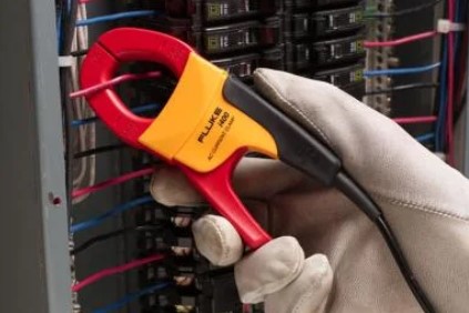
Another method of passing information between two electrical systems with separate grounds is the use of a Hall-effect sensor, which detects inductance and does not require direct contact with the signal in question and does not violate the isolation barrier. The most common place you may have seen this being used is in a current sense probe (like the clamp shown).
Capacitors
Reasons
There are good reasons, discussed here, why capacitors aren't a particularly good isolation mechanism, but if you need "something", but not full isolation, they might be worth considering. They are also discussed here because it plays into their overall role in AC/DC circuits.
Another method of achieving isolation is the use of series capacitors. As capacitors are permissible to AC signal, this can be a somewhat effective method of isolating portions of the electrical system from mains (think 120V AC). The reason this isn't a common method is that the isolation is less robust than the transformer method, as a transformer's failure mode is an open while one of a capacitor's failure modes is a short, and one of the purposes of creating galvanic isolation from the mains is such that in the event of a failure the user is safe from a effectively limitless current source.
Opto-isolators
Alternative Names
Opto-isolators are also called opto-couplers (what?), optical isolators, or even photo-couplers. These are all the same basic thing: something that emits light and something that detects light.
When working with signal-level circuits, an opto-isolator is one of the easiest ways to separate two parts of a circuit with different potential on he ground. For example, if you have one part of your circuit that's operating at 48V, but the rest is 3.3V, then you can use an opto-isolator to communicate signals across that boundary.
Altium has a great write-up of how to choose an opto-isolator and how to understand the data sheets.
Current Transients
Short Circuit & Ground Faults
Put simply, a short circuit is an unintended path that current can traverse, typically with little or no resistance. This typically results in substantial (excess) current flowing. This is bad. A ground fault is a specific kind of short circuit where electricity travels to ground outside the design’s intended path.
Current Transients
Occur momentarily in response to a change in the equilibrium of a circuit and frequently when power is applied to, or removed from, a circuit.
Circuit Overload
Occurs when an electric circuit is carrying more current than it's designed to handle, potentially creating a fire hazard due to overheating.
Reverse polarity
In all DC circuits, there is a normal direction of current flow, and if you accidentally connect something reversed from this normal flow, this can cause substantial issues. Take, for example, a common barrel jack power has a tip and a sleeve component. In sane connectors, the tip is the positive, but not all connectors are sane, and I have seen plenty of power supply "wall warts" that have them reversed. Plugging that into something will cause you to have a bad day.
Voltage Transients
Electrostatic Discharge
Back EMF
The voltage across an inductor is caused by a change in current which causes a change in the magnetic field within/around the coil. This change self-induces a voltage in the inductor. The polarity of the induced voltage always opposes that of the change in applied voltage. This is so that current will stay constant. This means when you remove the current from the inductor, it will get very angry, and you will get a spike of voltage (hundreds of volts, typically) reversed in polarity from the normal flow. This is bad because: 1) it can cause electromagnetic interference, which can in turn either cause the device itself to act weird or it can have a negative effect on nearby systems, and 2) if the spike in voltage is more than the system is designed to tolerate, it can cause significant or even catastrophic damage to the device itself.
Looking at the circuit below, you can click on the button and see what happens to the circuit when the magnetic field of the inductor collapses.
One of the best ways to protect against this back EMF is a snubber network. A snubber is a device/circuit that is used to limit (snub) voltage transients in circuits. Often there can be a sudden interruption of current flow, which drives a significant rise in voltage across a device. This can lead to both EMI, but also potential damage to the device due to back EMF. There are three major types of snubbers you can use. The simplest is a snubber diode. The more complicated is an RC snubber, and while it's marginally more complicated, it is also better behaved. Finally, you can build one out of solid-state (semiconductor) components, typically using a pair of Zener diodes.
Snubber Diode
Alternate Naming
Snubbers can also be called flyback protection, for example, a flyback diode. They can also just be called a suppression diode.
Flyback is a sudden voltage spike across an inductive load when its supply current is suddenly interrupted. It originated in its use in early CRT technology.
A snubber diode is the simplest possible solution and typically works well in DC circuits. It leverages the diode as a rectifier. We wire the diode in parallel with the load (say a relay), but set so that it doesn't conduct under normal use.
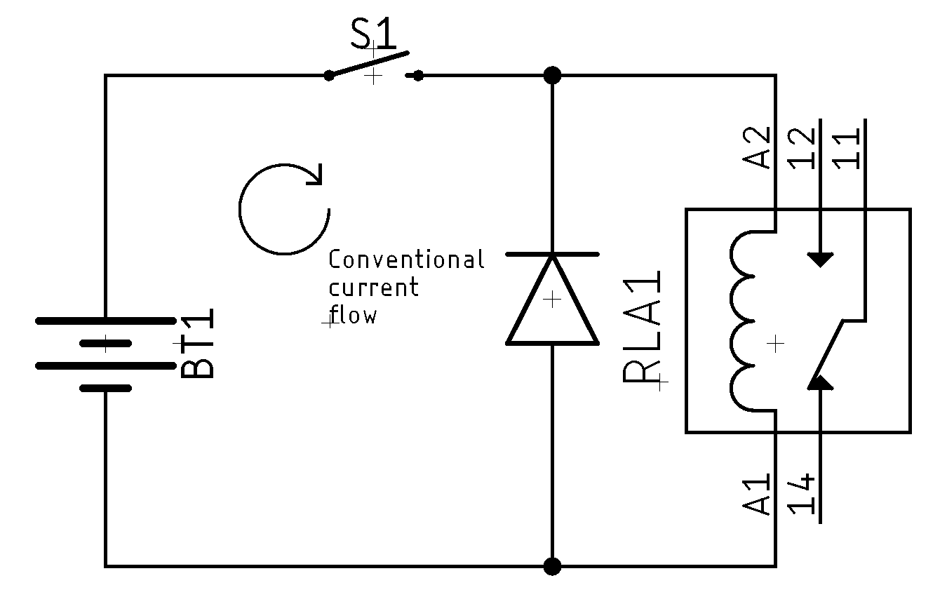
When current is interrupted, the magnetic field of the inductor (the coil in a relay) collapses, causing back EMF. This can drive a big spike in voltage. With the snubber diode, the inductor's current flows through the diode instead, and the energy is slowly released via the diode's inherent voltage drop.
Possible Problems
One reason that snubber diodes aren't that popular is that they are slow. Because of this, the inductor can stay active longer than you want. For example, it can cause the turn-off time of a relay to increase substantially.
You can watch this great video discussing it in more detail, or you can also just play with this little circuit here:
RC Snubber
RC snubbers operate on a similar principle to diode snubbers and are more "popular" in the industry as they work with both AC and DC systems. Since the voltage across a capacitor cannot change instantly, any voltage spikes are mitigated. An example, using the above basic schematic is:
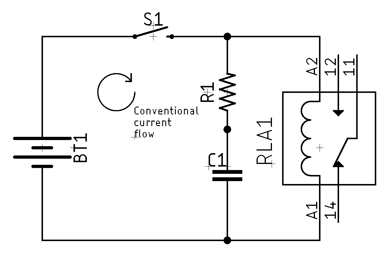
Unlike a diode snubber, there's some calculations you'll need to do to choose R and C correctly. This is quite complicated, and so I generally just use a diode snubber unless the timing is critical. Here's a version you can play with:
Load Dump
Load dump refers to what happens to the supply voltage when a load is removed. If a load is removed rapidly (such as when the battery is disconnected), the voltage may spike before stabilizing and damage electronic components. In a typical 5V circuit, load dump can rise as high as 60V and take 400 milliseconds to decay – more than enough to cause serious damage.
Comments or Questions?
If you have any comments, questions, or topics you'd like to see covered, please feel free to either reach out to me on Mastodon (link below) or open an issue on Github.